


From the sensor straight to intelligent decisions
Modern automation systems generate more sensor data than ever before, yet the path to the higher-level controller is often the bottleneck. TEConcept’s IO-Link Aggregator Device solves this problem by performing signal processing, data fusion, and simple control logic directly in the field before a single byte reaches the PLC.
IO-Link – explained briefly:
IO-Link (IEC 61131-9) is an internationally standardized communication protocol for the lowest level of the automation pyramid: the connection between a controller (SPS/PLC) and individual sensors or actuators in the field. Put simply: IO-Link replaces analog 4–20 mA signals with a digital, bidirectional point-to-point connection—via standard off-the-shelf three-wire cables up to a maximum length of 20 meters.
An IO-Link master is the interface to the higher-level PLC. It provides multiple ports, each of which connects to an IO-Link device—for example, a pressure sensor, a photoelectric sensor, or a temperature probe. The master polls the devices cyclically and forwards the process data (PD) to the PLC. The PLC receives ready-to-use measured values—no raw signals, no manual conversion.
The key advantage over classic analog technology: each IO-Link sensor transmits not only its measured value, but also device identification, diagnostic information, and configurable parameters—all digital, noise-resistant, and without complex signal wiring. The so-called IODD (IO Device Description) is a vendor-neutral XML file that precisely describes which data a device provides—comparable to a device driver that automatically sets up communication.
IO-Link Device
Sensor or actuator with an IO-Link interface. Provides digital measured values and can be parameterized via software, e.g., switching point, measuring range, or diagnostic interval.
IO-Link Master
Typically manages 4–8 ports, cyclically polls the connected devices, and passes the process data to the PLC or a cloud gateway.
IODD (Device Description)
Standardized XML file per sensor type. Describes data structure, parameters, and diagnostics, enabling vendor-independent integration without manual configuration.
Architecture at a glance
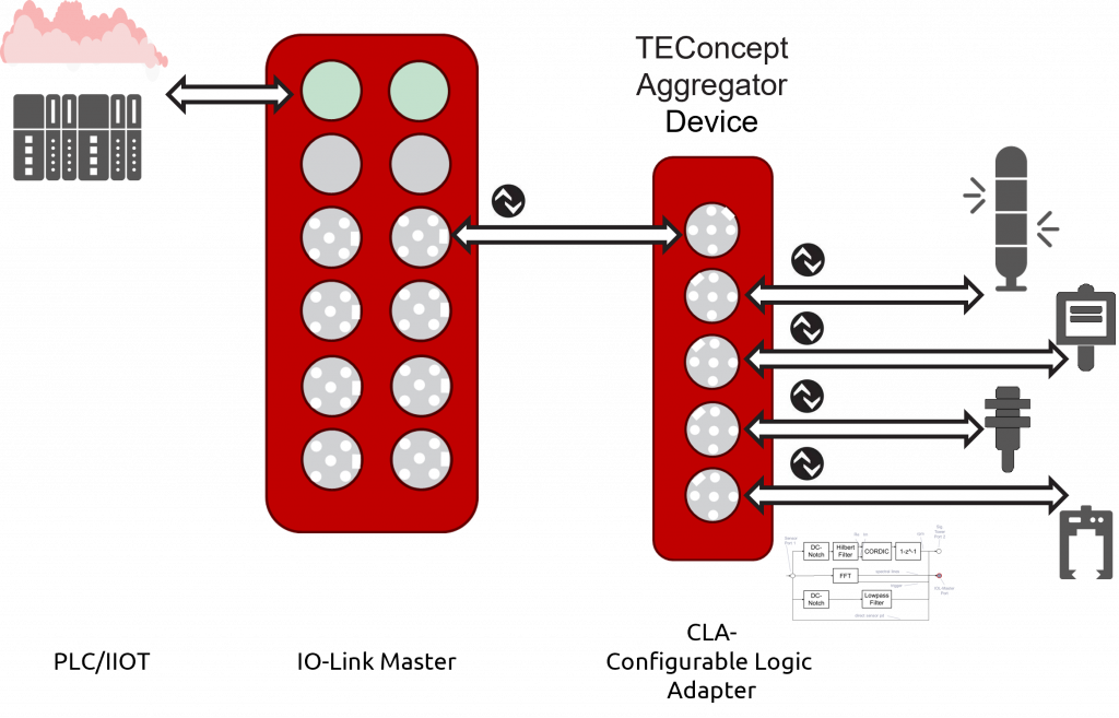
From the IO-Link master’s perspective, the Aggregator Device plays a simple role: outwardly, it behaves like a standard IO-Link device, registers with its own IODD, and provides structured process data. What happens inside is the real innovation: the device simultaneously operates four of its own IO-Link master ports, to which any sensors can be connected. The measured values from these four sensors are not simply passed through; instead, they are internally linked, filtered, and prepared before only preprocessed, relevant information is forwarded to the higher-level master.
The Aggregator Device therefore sits between the sensors and the actual IO-Link master and assumes the role of a field-level mini PLC, configurable without programming knowledge, directly in the system. Response times in the microsecond range are possible because data does not have to take the long path to the PLC and back.
4-in-1 IO-Link device hub
A standard IO-Link master has exactly one sensor per port. The Aggregator Device also occupies only one port on the master—but internally provides four fully featured IO-Link master ports. Four sensors, one cable connection to the PLC.
Real-time logic linking
Normally, IO-Link data must first go to the PLC, be processed there, and then return to the field. This cycle takes at least 10 ms. The Aggregator Device links sensor data locally in under 1 ms, ideal for time-critical shutdowns or control loops.
Digital preprocessing & signal conditioning for AI
Standard sensors deliver raw measured values—noisy and without context. The Aggregator Device’s internal CLA (Configurable Logic Adapter) filters, transforms, and analyzes these signals directly in the device, for example: DC notch, low-pass, Hilbert transform, and an FFT for frequency analysis. In addition to predefined default function blocks, new preprocessing blocks can also be defined.
Configuration without programming
The processing logic is assembled using a graphical PC application, similar to connecting blocks in a flowchart. The finished configuration is loaded onto the device via BLOB transfer (a mechanism defined in the IO-Link standard for larger data packets). Neither a firmware update nor programmed C code is required.
Use case: Condition monitoring of a rotary table
A compact rotary table in an assembly system is to be continuously monitored for imbalance and bearing wear—without expensive additional sensors or changes to PLC programming.
- Capture the raw signal: A simple IO-Link distance sensor (e.g., SICK DT35) continuously measures the surface of the rotating plate with a 2.5 ms cycle time.
- Synchronize speed: A second port reads the rotation angle of an encoder. The Aggregator Device correlates both signals in real time.
- Eliminate noise: The DC component is filtered out using a high-pass filter, and the mains frequency is removed via a notch filter. A low-pass filter smooths the remaining signal.
- Compute the spectrum: A 256-point FFT generates the complete frequency spectrum of the rotary table in about 1 second, making characteristic vibration lines visible.
- Forward in compressed form: Instead of transmitting thousands of raw values, the Aggregator Device sends only the relevant spectral lines to the PLC for alarm evaluation and/or to the cloud for trend analysis and predictive maintenance.
Signal-processing pipeline in detail
The Aggregator Device’s internal CLA (Configurable Logic Adapter) chains processing blocks like building blocks in a signal chain. Each block is described by a standardized descriptor file and can be extended with custom blocks; the system is open and not limited to the supplied algorithms:

In parallel, the second sensor port (rotation-angle signal) uses a CORDIC block to synchronize the spectral analysis with the actual rotational position. CORDIC is a computationally efficient algorithm for calculating angle functions (sin/cos) without a floating-point unit, ideal for embedded hardware with limited computing power. The result: the FFT spectral lines are assigned precisely to the angular position. A method that previously required specialized measurement technology or complex PLC programming now runs automatically in the Aggregator Device.
"A standard distance sensor becomes a fully featured condition monitoring system—without new hardware."
Dr. Otto Witte (Gründer)
Aggregator Device vs. classic approaches
| Criterion | Classic (PLC) | With Aggregator Device |
|---|---|---|
| Response time | Dependent on the PLC cycle (≥ 10 ms) | Directly in the device (µs–ms) |
| Data volume to the PLC | Raw data from all sensors | Only preprocessed characteristic values |
| PLC programming effort | High (filter logic, FFT, etc.) | No PLC changes required |
| Hardware ports on the master | 1 port per sensor | 4 sensors on "one" port |
| Condition monitoring | Additional measurement technology required | Integrated, at no additional cost |
| Cloud capability | Complex middleware | Direct via IO-Link → gateway |
Additional application scenarios
The Aggregator Device is not a niche tool; its principle can be used wherever multiple IO-Link sensors together reveal more than each one on its own:
Conveyor belt monitoring
Multiple IO-Link photoelectric sensors and a vibration sensor jointly provide information about belt tracking, fill level, and bearing health; the Aggregator Device consolidates all four IO-Link channels into a single status value that the PLC can evaluate directly.
Robot end effectors
Force, pressure, and position sensors on the gripper communicate via IO-Link. The Aggregator Device fuses their process data into compact grip-force feedback—without the robot controller having to poll each sensor individually.
Fluid process monitoring
IO-Link pressure, temperature, and flow sensors are logically linked directly in the Aggregator Device. Limit violations trigger local shutdown actions in under 1 ms, without having to wait for the PLC cycle.
Drive & spindle
Angle, speed, and vibration are captured via IO-Link and condensed into wear indicators. The compressed values are cyclically transmitted to the MES via the IO-Link master; raw data remains in the device.
Your product. Your name. Our technology.
TEConcept does not market the IO-Link Aggregator Device as its own end product, but as a complete technology blueprint for manufacturers, system integrators, and OEMs who want to integrate the principle into their own product line.
The blueprint includes the complete hardware design, firmware, and the PC configuration application. Customers receive everything they need to develop, manufacture, and distribute the Aggregator Device under their own brand name, including the option to add custom processing blocks and adapt the solution to specific applications.
White-label capable · Ready for immediate use
TEConcept provides the technological groundwork; you focus on your core business and customer relationships. The patented principle is made available to you for commercial use under an individual agreement.
Interested in an application consultation?

- +49 761 21443640
- +49 761 21443636
- info@teconcept.de
Would you like to have a look at your existing architecture and check without obligation whether the IO-Link Pathfinder is the right next step for your team?