



Home » IO-Link Products » IO-Link Diagnosis Tool
IO-Link Diagnosis Tool – Electrical and Logical IO-Link Signal Analysis
The IO-Link Diagnosis Tool is an IO-Link analyzer that electrically and logically examines the IO-Link signal. It is an indispensable tool for engineers and users of IO-Link technology to identify any type of problem in the IO-Link connection.
Can I try the IO-Link Diagnosis Tool before purchasing?
Functional Description
The IO-Link Diagnosis Tool is based on a high-speed multi-channel A/D converter that measures voltages and currents on both the C/Q and L+ lines. The captured data is transmitted via USB to the included Diagnosis Tool PC application and evaluated. The PC software runs on Windows 7 and newer.
IO-Link communication can be analyzed at the byte level, M-sequence level, protocol level, and even application level. In the latter case, the IO-Link communication is visible in plain text. Filter and search functions simplify error identification.
This enables visual monitoring in waveforms and eye diagrams for master and device signals.
Typically, the IO-Link Diagnosis Tool is inserted between the master and the device. However, an integrated IO-Link development master makes it possible to test devices without an external master. The entire communication is stored directly on a PC.
IO-Link Diagnosis Tool Functional Description
- Time-Accurate IO-Link Signal Analysis and Monitoring
- High-speed IO-Link synchronized ADC
- Time-accurate Software UART Decoding
- Optional hardware signal direction detection
- Byte-, frame-, protocol- or IODD-based decoding
- Advanced filter and search functions
- Image of all transmitted data
- Data storage image creation
- Storage on hard drive
- Analog signal view for UL+, IL+, UCQ, ICQ
- Serial decoding in analog waveform view
- Separate eye diagram view for Device and Master
- Interactive rulers for analog measurements
- New: Trigger-Out connection in V2.0
- Measurement data calibration
- Integrated Master
Advantages the IO-Link Diagnosis Tool brings you
- Fast and easy IO-Link problem analysis
- Logical and electrical diagnosis and analysis
- Suitable for the development of the application as well as its validation, market launch, and the field phase
Diagnosis Tool or IO-Link Spy – which fits when?
| Diagnosis Tool | Spy | |
|---|---|---|
| Type of connection for capturing IO-Link communication | Wired | Wireless (clipped on the IO-Link cable) |
| USB connection to the PC | yes | yes |
| Analysis of IO-Link communication (on byte/ M-Sequence/ protocol/ application level) | yes | yes |
| Analysis of the precise timing of each UART byte | yes | yes |
| Recording IO-Link byte streams to SD card | yes | no |
| Analog features (analog signal view for UL+, IL+, UCQ and ICQ, eye diagrams, analog triggers, calibration, …) | yes | no |
| Capturing an ongoing IO-Link communication (without interrupting it) | no | yes |
| Integrated IO-Link Master | yes | no |
| Works without any issues in environments with electromagnetic disturbance. | yes | no |
| Digital signals on the I/Q line do not affect the analysis of the IO-Link communication. | yes | no |
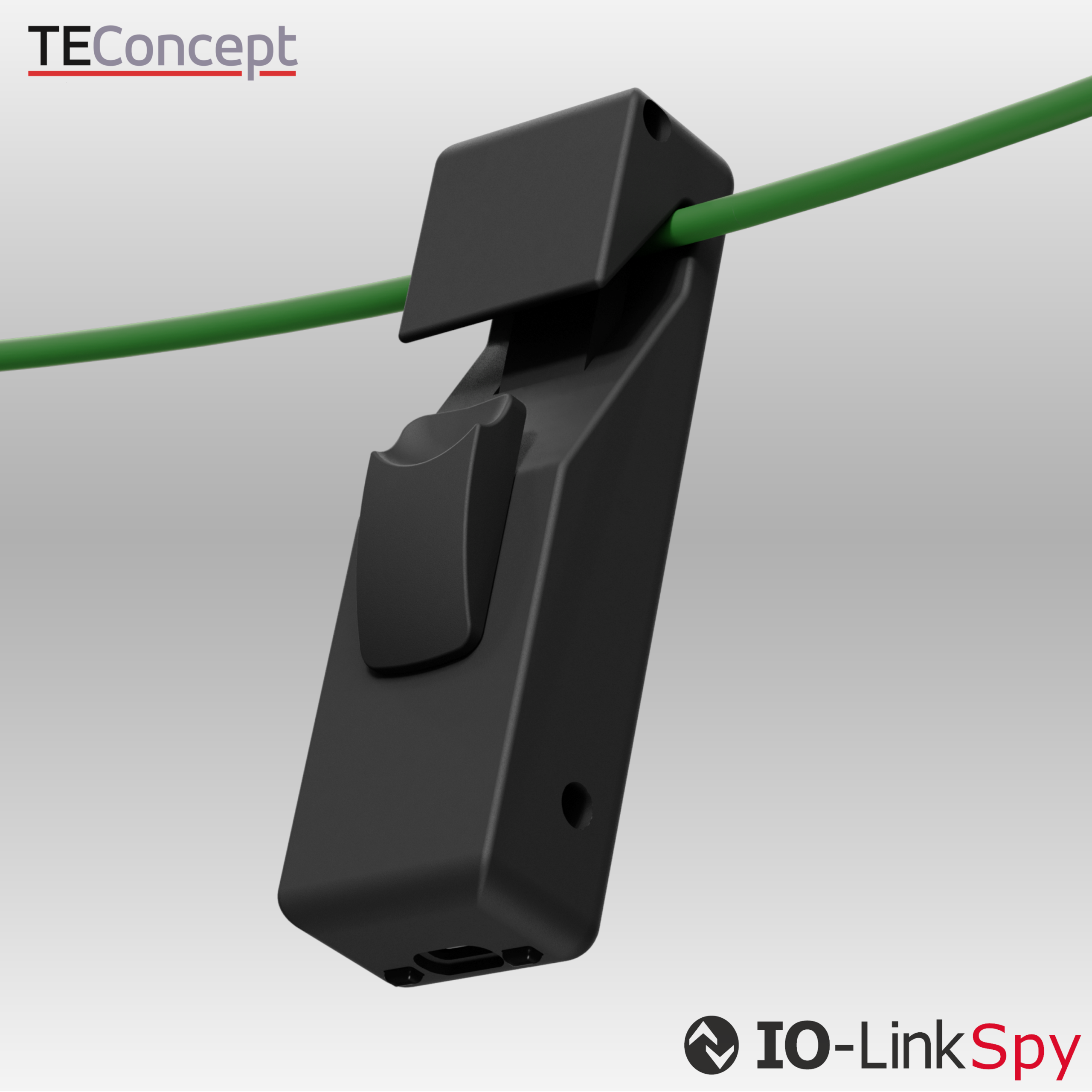
IO-Link Spy
Analyzes IO-Link communication at the bitstream level, making protocol errors, timing issues, and unexpected device behavior visible — indispensable for development and troubleshooting.
Contact

- +49 761 21443640
- +49 761 21443636
- info@teconcept.de