


Startseite » IO-Link Products » IO-Link Diagnosis Tool
IO-Link Diagnosis Tool – Electrical and Logical IO-Link Signal Analysis
The IO-Link Diagnosis Tool is an IO-Link analyzer that electrically and logically examines the IO-Link signal. It is an indispensable tool for engineers and users of IO-Link technology to identify any type of problem in the IO-Link connection.
Can I try the IO-Link Diagnosis Tool before purchasing?
Functional Description
The IO-Link Diagnosis Tool is based on a high-speed multi-channel A/D converter that measures voltages and currents on both the C/Q and L+ lines. The captured data is transmitted via USB to the included Diagnosis Tool PC application and evaluated. The PC software runs on Windows 7 and newer.
IO-Link communication can be analyzed at the byte level, M-sequence level, protocol level, and even application level. In the latter case, the
This enables visual monitoring in waveforms and eye diagrams for master and device signals.
Typically, the IO-Link Diagnosis Tool is inserted between the master and the device. However, an integrated IO-Link development master makes it possible to test devices without an external master. The entire communication is stored directly on a PC.
IO-Link Diagnosis Tool Functional Description
- Time-Accurate IO-Link Signal Analysis and Monitoring
- High-speed IO-Link synchronized ADC
- Time-accurate Software UART Decoding
- Optional hardware signal direction detection
- Byte-, frame-, protocol- or IODD-based decoding
- Advanced filter and search functions
- Image of all transmitted data
- Data storage image creation
- Storage on hard drive
- Analog signal view for UL+, IL+, UCQ, ICQ
- Serial decoding in analog waveform view
- Separate eye diagram view for Device and Master
- Interactive rulers for analog measurements
- New: Trigger-Out connection in V2.0
- Measurement data calibration
- Integrated Master
Advantages the IO-Link Diagnosis Tool brings you
- Fast and easy IO-Link problem analysis
- Logical and electrical diagnosis and analysis
- Suitable for the development of the application as well as its validation, market launch, and the field phase
Diagnosis Tool or IO-Link Spy – which fits when?
Both tools analyze IO-Link communication at the byte, M-sequence, protocol, and application level, including precise UART timing. The difference lies in the use case: the IO-Link Diagnosis Tool connects via cable and offers the broader feature set – analog signal display, eye diagrams, SD recording, and an integrated IO-Link master. It operates reliably even in EMC-heavy environments and remains unaffected by digital signals on the I/Q line. The IO-Link Spy, on the other hand, clips wirelessly onto the IO-Link cable and can passively sniff ongoing communication without interrupting it – ideal for troubleshooting directly during operation, when intervening in the wiring isn’t possible.
| Diagnosis Tool | Spy | |
|---|---|---|
| Type of connection for capturing IO-Link communication | Wired | Wireless (clipped on the IO-Link cable) |
| USB connection to the PC | yes | yes |
| Analysis of IO-Link communication (on byte/ M-Sequence/ protocol/ application level) | yes | yes |
| Analysis of the precise timing of each UART byte | yes | yes |
| Recording IO-Link byte streams to SD card | yes | no |
| Analog features (analog signal view for UL+, IL+, UCQ and ICQ, eye diagrams, analog triggers, calibration, …) | yes | no |
| Capturing an ongoing IO-Link communication (without interrupting it) | no | yes |
| Integrated IO-Link Master | yes | no |
| Works without any issues in environments with electromagnetic disturbance. | yes | no |
| Digital signals on the I/Q line do not affect the analysis of the IO-Link communication. | yes | no |
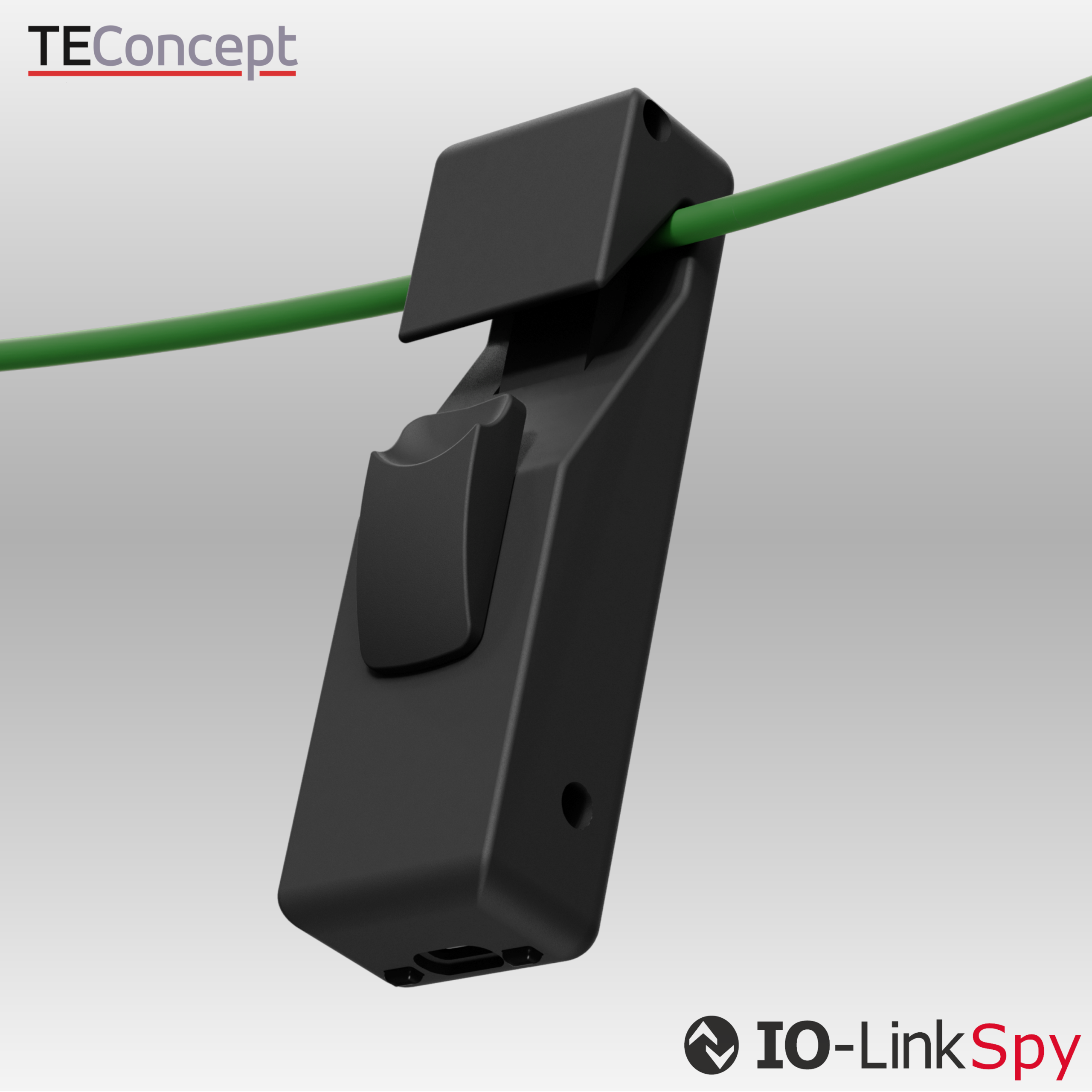
IO-Link Spy
Analyzes IO-Link communication at the bitstream level, making protocol errors, timing issues, and unexpected device behavior visible — indispensable for development and troubleshooting.
Contact

- +49 761 21443640
- +49 761 21443636
- info@teconcept.de